OR Gate
The OR gate can have two or more inputs and only one output. For a two input OR gate, the switch A and B are the two inputs of the gate and the bulb gives output Y. The ON switch stands for logic input 1 and OFF switch stands for logic input 0. The glowing bulb stands for logic output 1 and the non-glowing bulb for logic output 0.
In this case, when either A OR B or both the switches are ON, the supply voltage reaches the output and the bulb glows.
Truth Table
| A | B | Y |
| 0 | 0 | 0 |
| 0 | 1 | 1 |
| 1 | 0 | 1 |
| 1 | 1 | 1 |
The Boolean expression for an OR operation is represented as
Y= A + B and read as A or B.
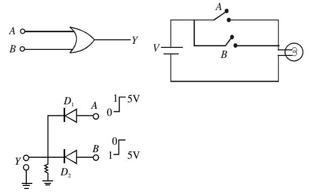
Realization of OR Gate
The cathodes of diodes D1 and D2 connected in parallel are grounded through a 5 kΩ resistance. The output is taken from the cathode and the two anode wires A and B serve as input terminals. When either A or B or both the terminals are connected to the positive terminal of the 5V battery, the respective diodes will conduct and potential at the output will be bout 5V i.e. logic 1. When both the switches are open, output will be 0 V i.e. logic 0.