Zener Diode as Voltage Regulator
The half-wave and full-wave rectifiers with filters are the simplest type of power supplies. These provide almost pure dc but have one deficiency. When load current is increased by decreasing resistance, the output voltage drops. This is because, when large current is drawn, the filter capacitor gets discharged more and its voltage across the load resistor reduces. Similarly, if the ac input changes, the dc output voltage also varies.
A supply with varying output voltage affects the performance of different devices being operated with it. To remove this deficiency, a Zener diode is used with simple power supplies which gives constant dc voltage. Such a circuit is called regulated power supply.
The Zener regulated voltage supply circuit consists of a Zener diode with breakdown voltage Vz. This will be equal to the stabilized output voltage VO. A suitable series resistance Rs is included to control circuit current and dissipate excess voltage. The anode of Zener diode is connected to the negative terminal of input supply, and the cathode is connected in series with Rs to positive terminal of input supply, that is, the Zener is connected in reverse bias condition.
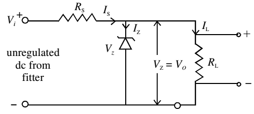
The load resistance is connected across the Zener diode. The Zener regulator will only operate if the input supply voltage to the regulator, Vi is greater than Vz. After breakdown, the voltage across it remains nearly constant and is independent of the current passing through it. The current Is flowing passing through Rs is given by
Is = (Vi –Vz)/Rs
This current divides in two parts: the Zener current Iz and load current IL. Applying Kirchoff’s law,
Is = Iz + IL
Iz = Is – IL
For Zener diode to operate, some current IZmin should always flow through it. Therefore, the load current IL should always be less than the main current Is. Typical value of IZmin may range from 5 mA to 20 mA.
If load current is zero, the entire Is will pass through Zener diode and output voltage VO will be equal to Vz. When some load current is drawn, say IL, the Zener current will decrease by the same amount but the output voltage will remain Vz.
Similarly, if the ac main voltage increases or decreases, the input voltage, Vi will increase or decrease accordingly. It will result in change of Is. Due to change in Is, the change in Vi will appear as a drop across the series resistance Rs. The Zener voltage Vz and hence VO will remain unchanged.
The power dissipation in Zener diode is given by
Pd = Vz × Iz
This dissipation should not exceed the maximum power dissipation rating recommended by the manufacturer for Zener diode.