A.C. Generator or Alternator
A generator consists of a loop of wire rotating in a magnetic field. As the loop is rotated along a horizontal axis, the magnetic flux through the loop changes.
φ(t) = B.A
If the angle between the field direction and the loop at any instant is denoted by θ, φ(t) can be written as
φ(t) = AB cosθ
When you rotate the loop with a constant angular velocity ω, the angle θ changes as
θ = ωt
φ(t) = AB cos ωt
Now, using Faraday’s law of electromagnetic induction, you can calculate the emf induced in the loop.
ε(t) = – dφ/dt = ω AB sin ωt
The emf induced across a coil with N number of turns is given by
ε(t) = N ω AB sin ωt
ε(t) = ε0 sin ωt
When a rectangular coil rotates in a uniform magnetic field, the induced emf is sinusoidal.
An A.C. generator consists of four main parts:
- Armature
- Field magnet
- Slip-rings
- Brushes
An armature is a coil of large number of turns of insulated copper wire wound on a cylindrical soft iron drum. It is capable of rotation at right angles to the magnetic field on a rotor shaft passing through it along the axis of the drum. This drum of soft iron serves two purpose - it supports the coil, and increases magnetic induction through the coil.
A field magnet is provides to produce a uniform and permanent radial magnetic field between its pole pieces.
Slip Rings provide alternating current generated in armature to flow in the device connected across them through brushes. These are two metal rings to which the two ends of the armatures are connected. These rings are fixed to the shaft. They are insulated from the shaft as well as from each other.
Brushes are two flexible metal or carbon rods (B1 and B2), which are fixed and constantly in touch with revolving rings. It is with the help of these brushes that the current is passed on from the armature and rings to the main wires which supply the current to the outer circuit.

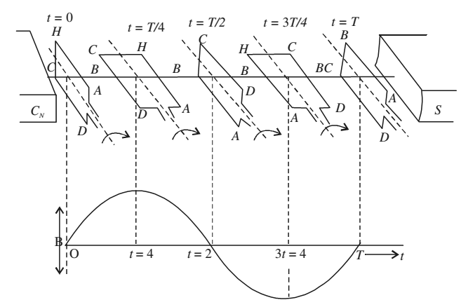
Suppose the armature coil AHCD rotates in the anticlockwise direction. As it rotates, the magnetic flux linked with it changes and the current is induced in the coil. The direction of the induced current is given by Fleming’s right hand rule.
Considering the armature to be in the vertical position and its rotation in anticlockwise direction, the wire AH moves downward and DC moves upwards, the direction of induced emf is from H to A and D to C i.e., in the coil it flows along DCHA. In the external circuit the current flows along B1RB2. This direction of current remains the same during the first half turn of the armature. However, during the second half revolution, the wire AH moves upwards while the wires CD moves downwards. The current flows in the direction AHCD in the armature coil i.e., the direction of induced current in the coil is reversed. In the external circuit direction is B2RB1. Therefore, the direction of the induced emf and the current changes after every half revolution in the external circuit also. Hence, the current produced alternates in each cycle.
The arrangement of slip rings and brushes creates problems of insulation and sparking when large output powers are involved. Therefore, in most practical generators, the field is rotated and the armature (coil) is kept stationary. In such a generator, armature coils are fixed permanently around the inner circumference of the housing of the generator while the field coil pole pieces are rotated on a shaft within the stationary armature.