Series LCR Circuit
The current through all the three circuit elements is the same in amplitude and phase but potential differences across each of them are not in the same phase.

The potential difference across the resistor VR = I0R and it will be in-phase with current.
Amplitude of potential difference across the capacitor VC = I0XC and it lags behind the current by an angle π/2.
Amplitude of potential difference across the inductor VL = I0XL and it leads the current by an angle π/2.
Phasor Diagram
Due to different phases, you can not add voltages algebraically to obtain the resultant peak voltage across the circuit. To add up these voltages, draw a phasor diagram showing proper phase relationship of the three voltages. The diagram clearly shows that voltages across the inductor and capacitor are in opposite phase and hence net voltage across the reactive components is VL – VC.

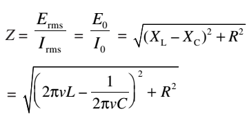
Impedance
The opposition to flow of current offered by a LCR circuit is called its impedance.
Resonance
Inductive reactance (XL) increases and capacitive reactance (XC) decreases with increase in frequency of the applied ac source. Moreover, these are out of phase. Therefore, there is a certain frequency vr for which XL = XC.
This frequency is called resonance frequency and at this frequency, impedance has minimum value.
Ζmin = R0
The circuit now becomes purely resistive. Voltage across the capacitor and the inductor, being equal in magnitude, annul each other. Since a resonant circuit is purely resistive, the net voltage is in phase with current (φ = 0) and maximum current flows through the circuit. The circuit is said to be in resonance with applied ac.
Power in a LCR Circuit
A capacitor connected to an ac source reversibly stores and releases electric energy. There is no net energy delivered by the source. Similarly, an inductor connected to an ac source reversibly stores and releases magnetic energy. There is no net energy delivered by the source. However, an ac generator delivers a net amount of energy when connected to a resistor.
Hence, when a resistor, an inductor and a capacitor are connected in series with an ac source, it is still only the resistor that causes net energy transfer.